72+ pages turning moment diagram of four stroke engine 3.4mb. Turning Moment Crank Effort Diagram for a 4-stroke I C engine Crank Angle TorqueN-m 0 Suction Compression Expansion Exhaust T T max mean Excess Energy Shaded area 2. If the mean torque T m will be assuming negative torque demand is negligible a 80 Nm b 120 Nm c 60 Nm d 40 Nm. Suction stroke 045 10 3 m 2 compression stroke 17 X 10 3 m 2 Expansion stroke 68 X 10 3 m 2 v Exhaust stroke 065 X 10 3 m 2 E a c h. Check also: diagram and understand more manual guide in turning moment diagram of four stroke engine 720 or 4 radians.
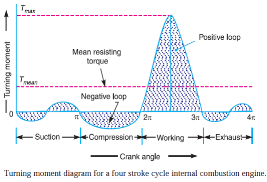
A turning moment diagram of the four-stroke engine as shown in the given diagram with the mean torque T m of 20 Nm. Since the pressure inside the engine cylinder is less than the atmospheric pressure during the suction stroke therefore a negative loop is formed as shown in Fig.

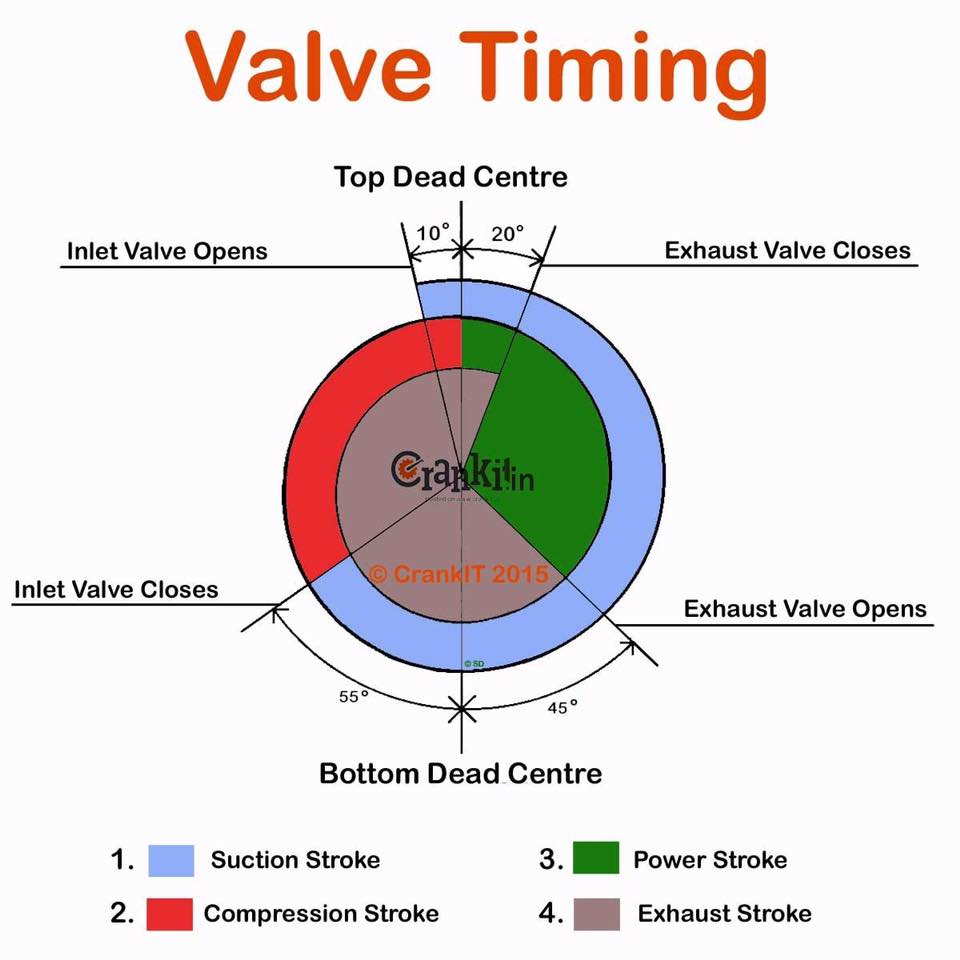
Valve Timing Diagram Of Two Stroke And Four Stroke Engines Theoretical And Actual Ingenieria Y Mecanica Automotriz
| Title: Valve Timing Diagram Of Two Stroke And Four Stroke Engines Theoretical And Actual Ingenieria Y Mecanica Automotriz |
| Format: PDF |
| Number of Pages: 231 pages Turning Moment Diagram Of Four Stroke Engine |
| Publication Date: April 2020 |
| File Size: 3.4mb |
| Read Valve Timing Diagram Of Two Stroke And Four Stroke Engines Theoretical And Actual Ingenieria Y Mecanica Automotriz |
 |
This diagram can be plotted progressively as explained below.

Turning Moment Diagram For A 4 Stroke CycleWatch More Videos at. All the stroke except power stroke consume the energy stored in the flywheel. We know that in a four stroke cycle internal combustion engine there is one working stroke after the crank has turned through two revolutions ie. Turning moment diagram for a four stroke cycle internal combustion engine. Turning Moment Diagram TMD for 4-stroke engines Video Lecture from Chapter Flywheel and Governors in Theory of Machine for Mechanical Engineering Students. We know that in a four stroke cycle internal combustion engine there is one working stroke after the crank has turned through two revolutions ie.
Solved In A 4 Stroke Ic Engine The Turning Moment During The Pr
| Title: Solved In A 4 Stroke Ic Engine The Turning Moment During The Pr |
| Format: ePub Book |
| Number of Pages: 324 pages Turning Moment Diagram Of Four Stroke Engine |
| Publication Date: May 2018 |
| File Size: 3.4mb |
| Read Solved In A 4 Stroke Ic Engine The Turning Moment During The Pr |
 |

Question And Answers Page 2 Mechanical Engg Diploma Simple Notes Solved Papers And Videos
| Title: Question And Answers Page 2 Mechanical Engg Diploma Simple Notes Solved Papers And Videos |
| Format: PDF |
| Number of Pages: 298 pages Turning Moment Diagram Of Four Stroke Engine |
| Publication Date: October 2019 |
| File Size: 2.6mb |
| Read Question And Answers Page 2 Mechanical Engg Diploma Simple Notes Solved Papers And Videos |
 |

Turning Moment Diagram
| Title: Turning Moment Diagram |
| Format: PDF |
| Number of Pages: 157 pages Turning Moment Diagram Of Four Stroke Engine |
| Publication Date: April 2019 |
| File Size: 1.9mb |
| Read Turning Moment Diagram |
 |

1 Turning Moment Diagram For A Single Cylinder Double Acting Steam Engine
| Title: 1 Turning Moment Diagram For A Single Cylinder Double Acting Steam Engine |
| Format: ePub Book |
| Number of Pages: 311 pages Turning Moment Diagram Of Four Stroke Engine |
| Publication Date: March 2017 |
| File Size: 2.6mb |
| Read 1 Turning Moment Diagram For A Single Cylinder Double Acting Steam Engine |
 |

1 Turning Moment Diagram For A Single Cylinder Double Acting Steam Engine
| Title: 1 Turning Moment Diagram For A Single Cylinder Double Acting Steam Engine |
| Format: ePub Book |
| Number of Pages: 338 pages Turning Moment Diagram Of Four Stroke Engine |
| Publication Date: June 2017 |
| File Size: 2.3mb |
| Read 1 Turning Moment Diagram For A Single Cylinder Double Acting Steam Engine |
 |

Carlos Humberto On Ingenierias In This Moment Word Find Turn Ons
| Title: Carlos Humberto On Ingenierias In This Moment Word Find Turn Ons |
| Format: ePub Book |
| Number of Pages: 349 pages Turning Moment Diagram Of Four Stroke Engine |
| Publication Date: October 2017 |
| File Size: 810kb |
| Read Carlos Humberto On Ingenierias In This Moment Word Find Turn Ons |
 |

Question And Answers Mechanical Engg Diploma Simple Notes Solved Papers And Videos
| Title: Question And Answers Mechanical Engg Diploma Simple Notes Solved Papers And Videos |
| Format: PDF |
| Number of Pages: 178 pages Turning Moment Diagram Of Four Stroke Engine |
| Publication Date: June 2020 |
| File Size: 5mb |
| Read Question And Answers Mechanical Engg Diploma Simple Notes Solved Papers And Videos |
 |

Flywheel
| Title: Flywheel |
| Format: eBook |
| Number of Pages: 283 pages Turning Moment Diagram Of Four Stroke Engine |
| Publication Date: November 2019 |
| File Size: 2.8mb |
| Read Flywheel |
 |

Turning Moment Diagram
| Title: Turning Moment Diagram |
| Format: ePub Book |
| Number of Pages: 211 pages Turning Moment Diagram Of Four Stroke Engine |
| Publication Date: July 2021 |
| File Size: 1.3mb |
| Read Turning Moment Diagram |
 |

Turning Moment Diagram For A 4 Stroke Cycle
| Title: Turning Moment Diagram For A 4 Stroke Cycle |
| Format: eBook |
| Number of Pages: 335 pages Turning Moment Diagram Of Four Stroke Engine |
| Publication Date: January 2017 |
| File Size: 1.6mb |
| Read Turning Moment Diagram For A 4 Stroke Cycle |
 |

Flywheel
| Title: Flywheel |
| Format: PDF |
| Number of Pages: 256 pages Turning Moment Diagram Of Four Stroke Engine |
| Publication Date: September 2017 |
| File Size: 1.3mb |
| Read Flywheel |
 |
The excess of energy generated during power stroke is stored in the flywheel. A negative loop is formed in the turning moment diagram of a 4 stroke IC engine because during suction the pressure inside the engine is reduced due to intake and has a lower value than the atmospheric pressure. We know that in a four stroke cycle internal combustion engine there is one working stroke after the crank has turned through two revolutions ie.
Here is all you have to to know about turning moment diagram of four stroke engine Turning moment diagram for single cylinder 4 stroke engine Since the pressure inside the engine cylinder is less than the atmospheric pressure during the suction stroke therefore a negative loop is formed as shown in Fig. During the expansion or working stroke the fuel burns and the gases expand therefore a large positive loop. Turning Moment Diagram TMD for 4-stroke engines Video Lecture from Chapter Flywheel and Governors in Theory of Machine for Mechanical Engineering Students. Turning moment diagram question and answers mechanical engg diploma simple notes solved papers and videos flywheel flywheel carlos humberto on ingenierias in this moment word find turn ons valve timing diagram of two stroke and four stroke engines theoretical and actual ingenieria y mecanica automotriz Turning Moment Or Crank Effort Diagram TMD Turning moment diagram is a graphical representation of turning moment or torque along Y-axis versus crank angle.


0 Comments